Copyright 2005-2026 Cabinet Planner LLC
Upper cabinet type:
Entering 1 in this box will plan upper cabinets with the top and bottom of equal lengths. If you set scribe to a side of the cabinet, the program will only shorten the box by that amount.Entering 2 will run the bottom through on sides with scribe applied to them and shorten that sides length by the amount of the bottom rail minus the bottom lip size.
Bottom lip:
The size you enter in this box is the amount that the bottom rail sticks up above the bottom of the cabinet. The size entered in this box on the upper cabinet standards windows will be applied to all upper cabinets. The size entered in this box on the base cabinet standards window will be applied to all base cabinets, vanities, and tall cabinets.
Deduct for partition height:
This setting will let you adjust the height of base cabinet partitions to allow for stretchers to run above them without having to cut a notch for them.
Drawer box settings:
Deduct for width-This is how much to deduct from the drawer opening for figuring the overall width of the drawer box.
Deduct for height-This is how much to deduct from the drawer opening for figuring the height of the drawer box.
Deduct for depth-This is how much is deducted from the cabinet depth for figuring drawer box depth.
Rabbet depth for sides-This is how much the front and back is rabbeted into the sides of the drawer box.
Dado depth for bottoms-This is how much the bottoms are dadoed into the sides, fronts and backs of the drawer boxes.
General:
Location assist- Checking this box will fill in the location box with the location + the width of the last saved cabinet in a job. This works only when planning a lob from left to right.
Click & Drag- Checking this box will keep the click & drag feature enabled.
Shelf edge thickness- amount to deduct from overall shelf depth
Deduct for shelf length- lets you set how much is deducted from adjustable shelf's length
Deduct for shelf depth- lets you set how much is deducted from adjustable shelf's depth
Door stile and rail cutter depth- This size is used to figure how much to add to the rails of doors.
Tenon length for doors-The size entered in this box is doubled and added to all door and raised panel rails and middle rails or stiles where appropriate
Round to nearest 1/16- Entering 'Y' will tell the program to trim sizes to the nearest 1/16. Entering 'N' will have the program give exact sizes. If they are an exact fraction, then that fraction will be given down to 1/32. Entering 'X' will give you decimals only.
Tenon length for face frames- The size entered in this box will be doubled and add to all appropriate face frame sizes
When calculating Master lists- These two check boxes tell the program what to do with the master lists when calculating them. If you wish to edit a list before printing it, send it to the main window then when done editing it, press the print list button
Arched doors-The top box is for the width of the top rail and the second box is for the height of the arch.
Side to face frame dado depth-This is for people who dado their face frames to the cabinet box. The size entered here will be added the depth of the cabinet sides. Leaving this box blank will plan the cabinets normally.
Inset Back Depth:
Entering Zero in this box will make the program deduct the thickness of the backs from the side, tops, bottoms and partitions.
Entering a value greater than Zero will make the program deduct that amount from the tops, bottoms and partitions. Sides will be kept full depth.
Adjusting elevation color:
Click the file menu and select Set Elevation Colors
A selection window will open, click the OK button next to the item you wish to adjust the color for. A basic color dialog window will open. You may choose one of the these basic colors or click the Define Custom Colors>> button to fine tune your color.
To adjust the colors in the custom color window, left click on the large color box and slide your mouse around until you find a color close to what you want. Then click on the arrow on the right to adjust the color further. Also, you may type the values you want in the six number boxes on the right. Click the OK button and your color will be saved. The Add To Custom Colors button is not supported by the program. If you wish to print your elevations in black and white, un-check the Color On box in the selection window.
Adding hardware:
To add hardware to the elevation view of the cabinets a few standards must first be set.
In the Set All Other Standards window enter the Knob diameter, Pull size and length and whether you want knobs or pulls on the doors and drawers. The Pull size is the diameter of the pull.
In each of the Upper, Base and Tall standards windows, enter the location the hardware should be placed on the doors. This can be individually adjusted for each cabinet.
The cabinet editing window has a Door Hardware button for cabinets with doors. Clicking this button will open another window where you can change the locations for the hardware if needed. In this window you can change from a knob, pull or no hardware. For each level of doors you can set whether the hardware is on the top, middle or bottom. When the cabinet is set to have one door per opening there will be two boxes for each door to specify putting the hardware on the left or right side of the door. If the
opening is set for two doors the hardware will automatically put on the inner sides of the doors.
Drawer hardware can be changed from a knob, pull or no hardware in the cabinet editing window. The drawer hardware is applied to the center of all drawers. It is not applied to false fronts with the exception of the sink base to allow for tipout trays.
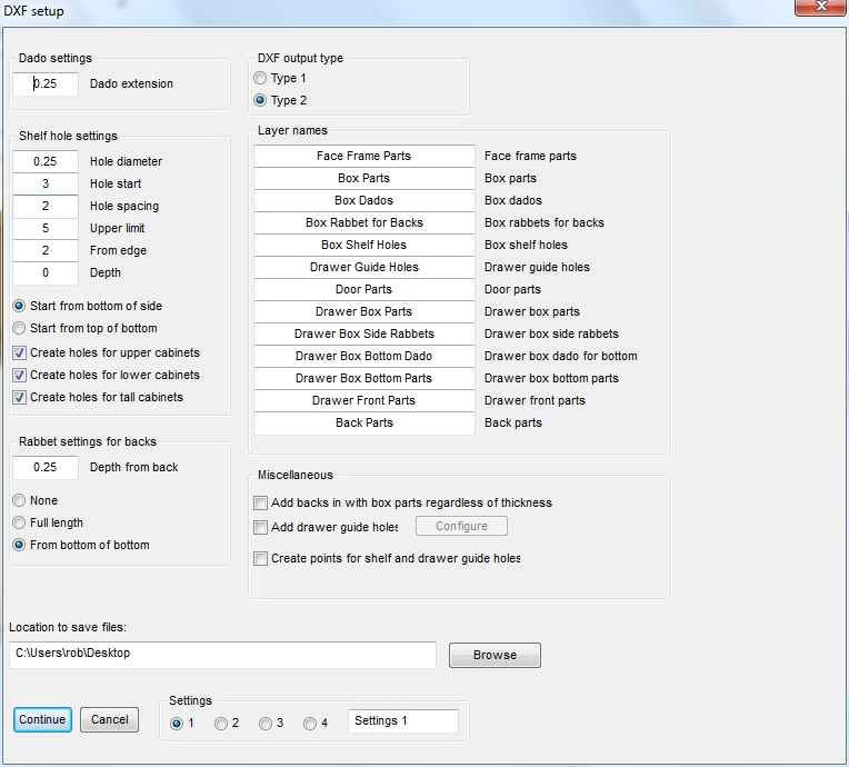
DXF Settings:
Setting up and using the DXF output is pretty straight forward. The setup window gives a few options for what is added to the file and how it is applied. Once you have it setup press the CALC button in the toolbar and select the panel layout button next to the material to be nested.
Once the program gathers all the parts a window will open asking for the size of the source panel and a few other settings. After entering your sizes press the OK button and the main optimizer window will open. Put a check in the box for DXF file output and press one of the method buttons. After cycling through all the panels for each material a file dialog window will open for you to select a name and location for the DXF file and press save. The file will be created and you can then import it into your toolpathing software.
Settings
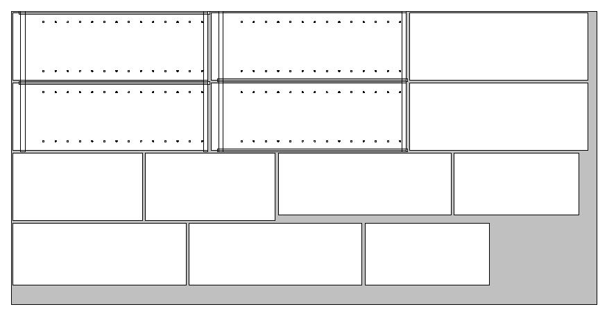
Sample output with dados, rabbets and shelf holes: